Powermeter
DIY: RF-Powermeter with AD8317 and Arduino
Ideas and plan
As C language was familiar to me, I had the idea of building a RF-Powermeter with an Arduino and a Log-Amp AD8317 from Analog Devices.
The RF-chip on a small pcb was bought at the DARC shop. It just needs DC power and outputs DC voltage, which easily can be read from an Arduino analog pin. For better adjusment, the Arduino A_ref pin was fed with a reference diode 4.096V. On programside that seemed easy first, but some struggling followed. The voltages of the Log-Amp were shown dependant on the RF-frequency, so an EEPROM was chosen to hold a comparison table.
Some Frequencies in MHz values as integers were planned:
freqs: [1, 10, 30, 50, 144, 900, 1296, 1900, 2320, 2400, 3600, 5800, 8000, ]For every frequency 14 voltage levels as integers were foreseen in the storage array.
Where to get the values from? My friend had an old signalgenerator together with an R&S URV4 powermeter for comparison, so we started to measure mV in Arduino for some RF-Levels:
levels: [ -60, -55, -50, -45, -40, -35, -30, -25, -20, -15, -10, -5, 0, 5, ]Storing Freqs and levels in a 2-dimensional array was easy, 1st column as freq, other columns hold the different power levels. That was easy, but some stupid work to fiddle all the values on the signalsource. Unfortunately the signalgenerator was not able to increase the frequency above 1 GHz, there is still some work left. The measured voltage is interpolated over the table values.
How to handle the baby?
The device needs some handling knob to select the frequency, a rotary switch was choosen. To see setting and the measurement values, a LCD display shoud fit. To keep the user informed about working or not, one character shows a rotating line, an inspiration from a very old boot screen …
Of course, the usb connection is not only used to power the system but also for handling via a menu on the serial tty. Best fit proved minicom to work with it.
The Hardware was screwed together:
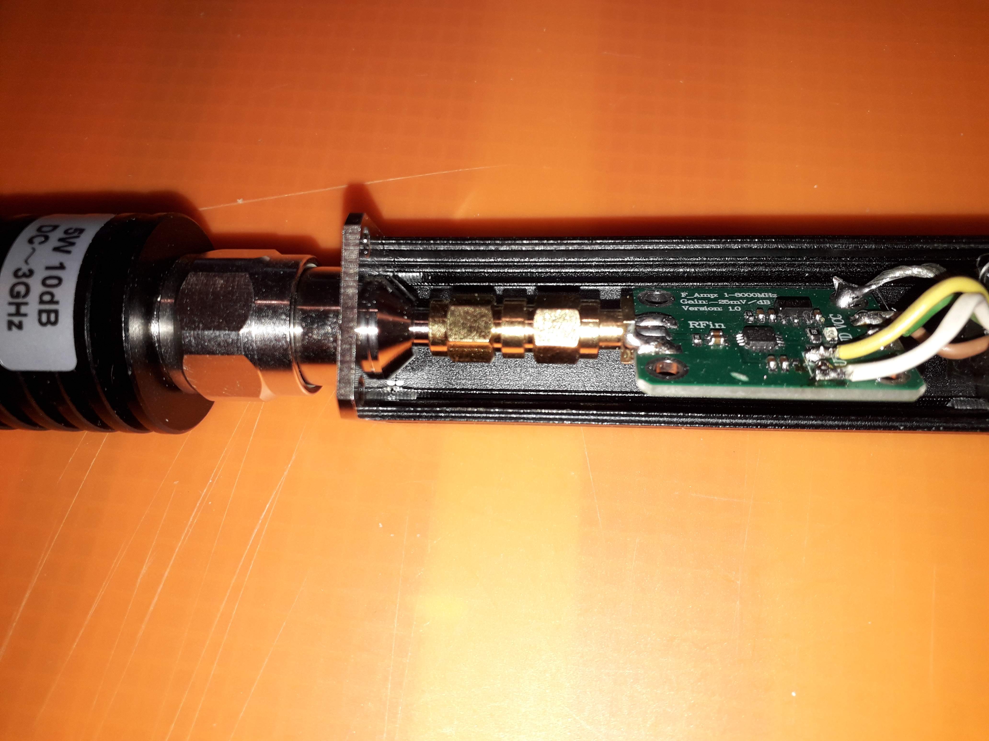
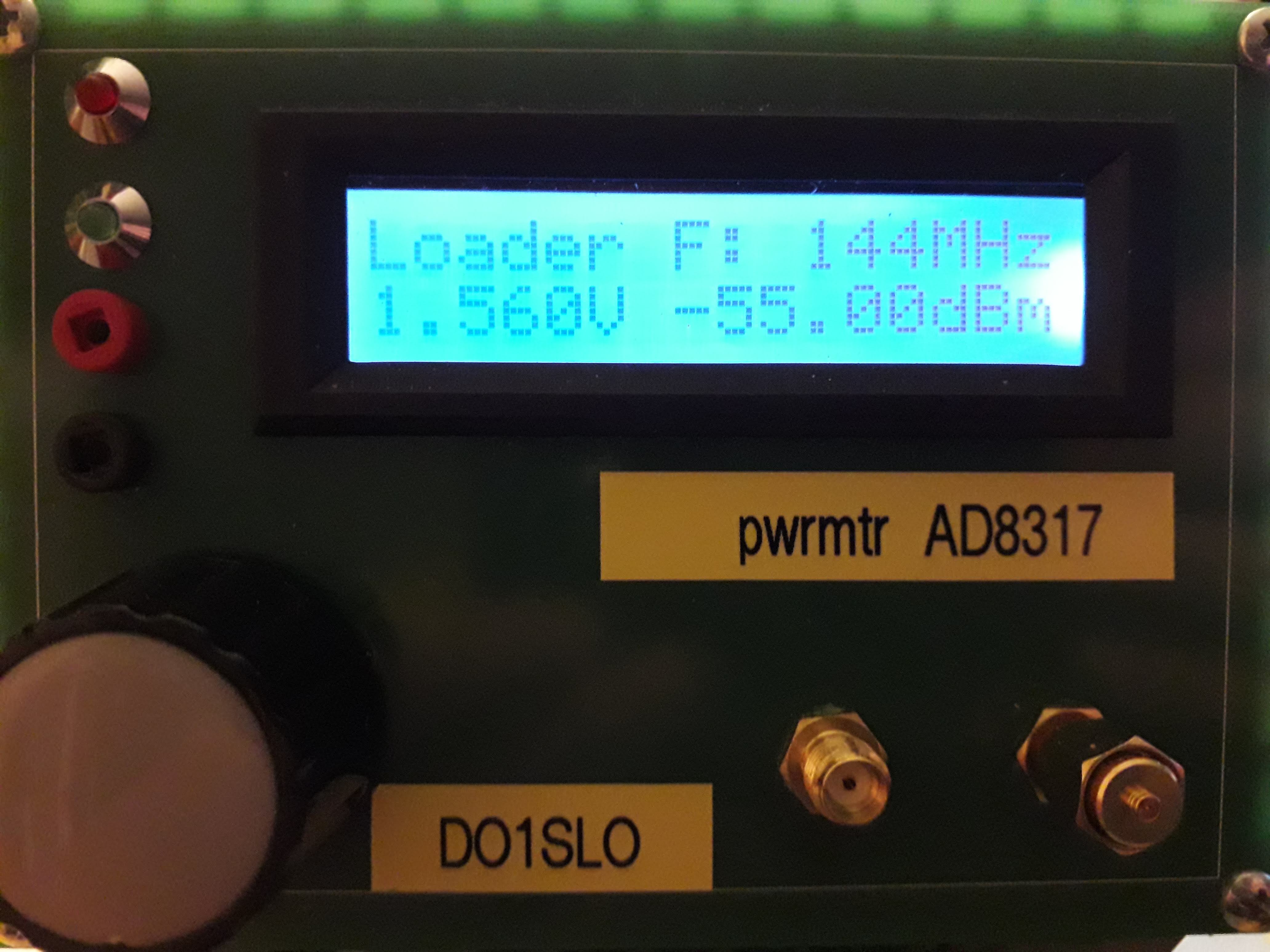
Table loading into EEPROM needs another Arduino program due to low space inside …
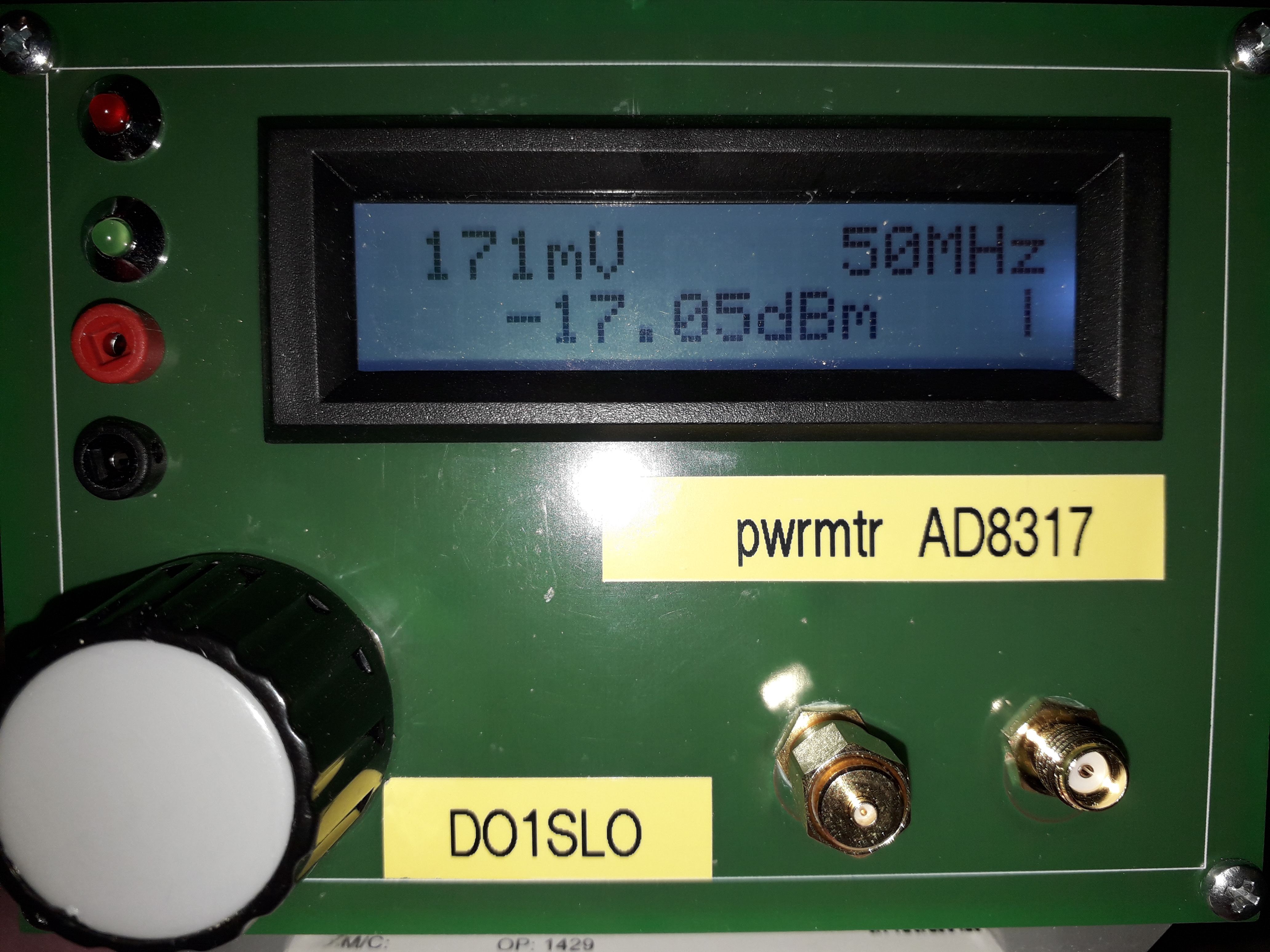
After loading the table, the normal program is run connected to the signalgenrator:
The functionality via usb-connection grew over time, peak and average measurements were not written in the beginning.
Here is an excerpt from the source showing the menue when asked for by pressing letter ‘h’ in the terminal program:
void help() {
    Serial.println();
    Serial.println(F("serial console commands:"));
    Serial.println(F(" z: show power diff to actual value "));
    Serial.println(F(" Z: do not show power diff"));
    Serial.println(F(" t: toggle measurement serial output on/off"));
    Serial.println(F(" F: next frequency"));
    Serial.println(F(" f: prev frequency"));
    Serial.println(F(" a: Normal Mode, no median, no peak values"));
    Serial.println(F(" A: Median Mode"));
    Serial.println(F(" B: reset min/max values"));
    Serial.println(F(" X: reset correction_voltage to 0V prepend to 0dB"));
    Serial.println(F(" P: -1 dBm prepended att. up to 60dBm"));
    Serial.println(F(" p: +1 dBm prepended att. up to 60dBm"));
    Serial.println(F(" C: -1 mV correction_voltage"));
    Serial.println(F(" c: +1 mV correction_voltage"));
    Serial.println(F(" E: -10mV correction_voltage"));
    Serial.println(F(" e: +10mV correction_voltage"));
    Serial.println(F(" v: version"));
    Serial.println(F(" b: set backlight"));
    Serial.println(F(" n: sensor_name"));
    Serial.println(F(" D: dump all values"));
    Serial.println(F(" d: dump actual values"));
    Serial.println(F(" h: this help text"));
    Serial.println(F("Enter command: "));
}
The rotating character is very useful, perhaps needs some explanation?
// backslash needed for rotator is the first user defined char
byte backslash[8] = {
B00000,
B10000,
B01000,
B00100,
B00010,
B00001,
B00000,
B00000
};

void rotator() {
    static char rotator_value[] = {(char)0, '|','/','-' };
    static unsigned int cntr;
    if (milli_timer < rotate_timer) return;
    rotate_timer = milli_timer + ROTATE_TIME;
    if (++cntr >= sizeof(rotator_value)) cntr = 0;
    lcd.setCursor(ROT_X, ROT_Y);
    lcd.print((char) rotator_value[cntr]);
}
And after some more or less struggle it worked. I was very happy to close the box somewhen in 2021 …
Today I have forgotten almost everything about it, sorry.